| Home | ||
PA tubes changed from 6JS6C sweep tubes to 6146B following the QST article of May 1999 and
addendum (Hints & Kinks) September 1999. Original QST article by Roger Davis ZS1J.
|
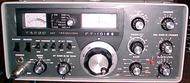
Yaesu FT-101EE |
Original Sweep tube sockets |
 |
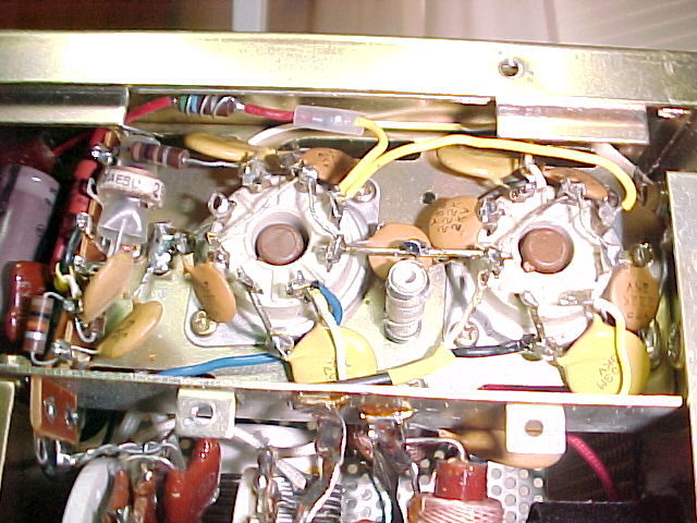 |
Ceramic octal sockets The QST article was followed with some exceptions. 6146B tubes were not used, 6883B tubes were used instead. The 6883B is the equivalent of a 6146B with a 12 Volt filament. Each cathode pin was bypassed with a .002 2KV disc capacitor. Each screen grid was bypassed with a .01 3KV disc capacitor. C-16 to the RCA jack was removed to make room for bypass capacitors at the socket. Filaments rewired for 12 volts, each filament bypassed with a .01 3KV disc capacitor. None of the Yaesu capacitors removed from the PA sockets were reused. |
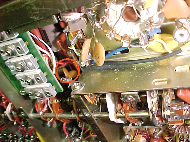
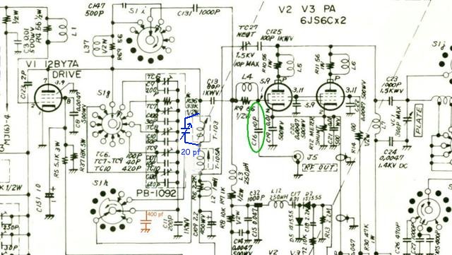
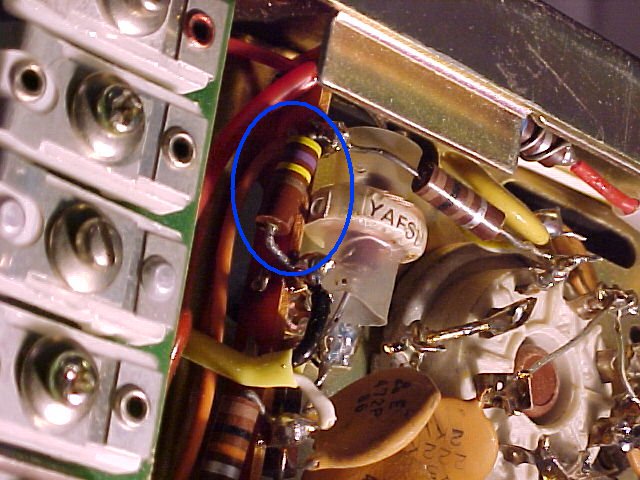
| 400 pf disc capacitor (Red circle) added to neut feedback in order to allow variable neut capacitor to be midrange when PA is neutralized. |
 |
 |
20 pf Variable trimmer added across coil T-103 required to tune 10 meter band. |
| Schematic with new modifications indicated. 400 pf (Red) required in this transmitter to allow variable neutralizing capacitor (TC-27) to be within range. September 1999 QST addendum suggested 2000 pf. 20 pf variable trimmer (blue) added across T-103 to permit 10 meter tuning. C16 (Green) to RF out RCA jack removed since I do not use it and it provided additional room for ceramic octal sockets and bypass capacitors. |
 |
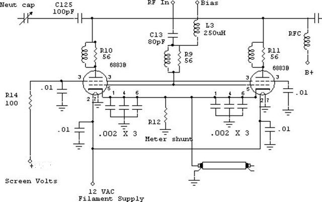 |
New PA Schematic. |
Modification revisited 2011. |
 |
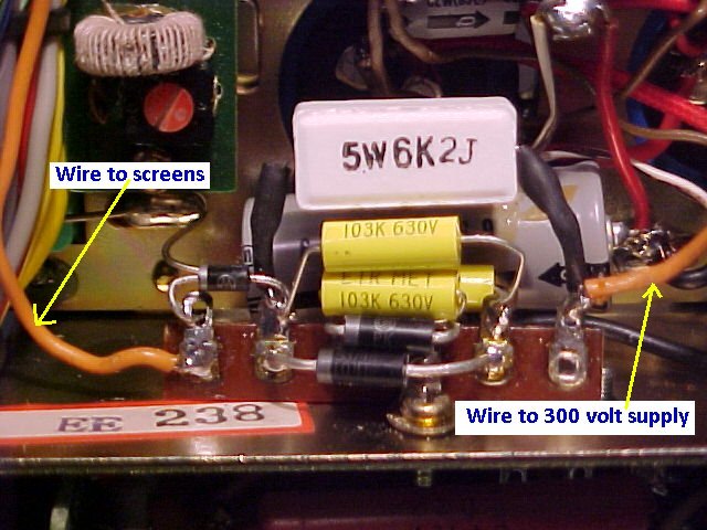 |
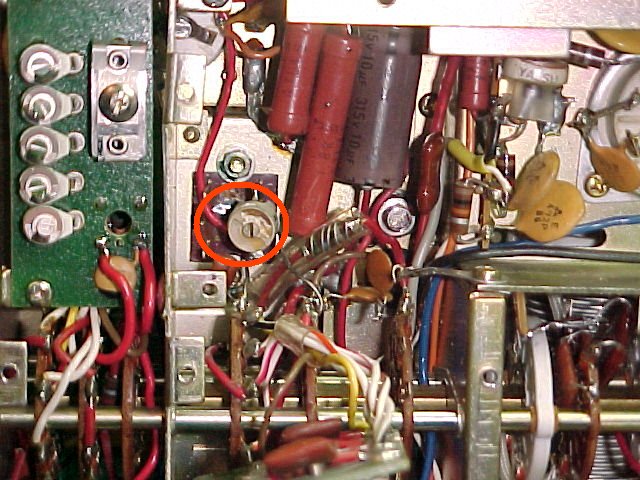
New parts placement. A small terminal strip was mounted to hold the components. |
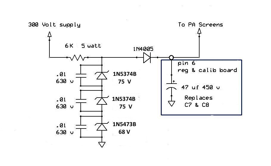
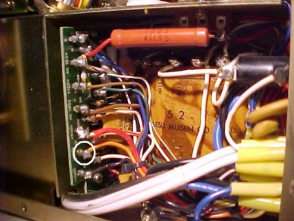
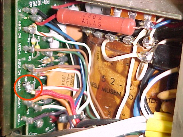
| Orange wire goes from the 6K resistor to the 300volts pin 4 of the Accessory socket J14. | 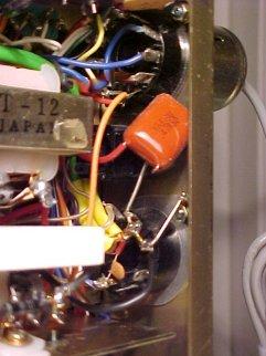 |
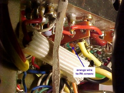 |
Orange wire from regulated circuit goes to the PA screens terminal strip. |
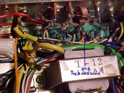
| Pin 6 of the Regulator board goes to C7and C8 to filter the original 160 volt screen supply. Three orange wires land on pin 6. Two have been cut free, the wire to the accessory socket and the wire to the 160 volt power supply. The remaining wire goes to the PA screens terminal strip. In addition, on the regulator board, C7 and C8 22 uf 250 volt capacitors have been replaced by a single 47uf 450 volt capacitor. |
 |
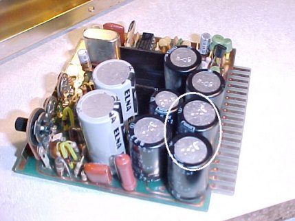 |
Regulator Board. C7 and C8 that have been removed and replaced by a single 47 uf 450 volt capacitor. |
| 160 volt power supply. Orange wire unsoldered and stored. This removes 160 volts from the original wiring, the orange wire is open at the far end. |
 |
| Neutralizing -Cold Neutralize- Remove the Accessory plug from the socket on the chassis rear apron (removes filament voltage from PA tubes). Turn on AC and Filaments, terminate the antenna jack in 50 ohms, connect oscilloscope across 50 ohm load on antenna. With the transmitter on 10 or 15 meter band, key the rig (MOX in TUNE mode), advance the carrier control 1/3 to 1/2 rotation, peak preselect, Plate and Loading for maximum indication on the scope, minimize the scope display with the Neutralizing capacitor TC27. Re-peak the Plate and Loading for maximum indication, minimize display with Neut capacitor, repeat the process until Plate and Loading have no increase on the display when the neut cap has the display minimized. If Neutralizing capacitor TC27 reaches full mesh or wide open, adjust the value of shunt capacitor across C11. 400 Pf worked on this transmitter, 2000 pf was the suggested value from the Sept 1999 QST article. |
 |
Below is an alternate method of Neutralizing. Discharge all HV Power Supplies. Remove 600V B+ from the PA plate, unsolder Red wire. |
| Remove screen grid voltage from PA, unsolder orange wire at pin4 of ACC socket J14 (300volts). Turn on AC and Filaments, terminate the antenna jack in 50 ohms, connect oscilloscope across 50 ohm load on antenna. With the transmitter on 10 or 15 meter band, key the rig (MOX in TUNE mode), advance the carrier control 1/3 to 1/2 rotation, peak preselect, Plate and Loading for maximum indication on the scope, minimize the scope display with the Neutralizing capacitor TC27. Re-peak the Plate and Loading for maximum indication, minimize display with Neut capacitor, repeat the process until Plate and Loading have no increase on the display when the neut cap has the display minimized. Shutdown the transmitter, discharge high voltage power supply voltages. Resolder Plate and Screen wires. If Neutralizing capacitor TC27 reaches full mesh or wide open, adjust the value of shunt capacitor across C11. 400 Pf worked on this transmitter, 2000 pf was the suggested value from the Sept 1999 QST article. |
|
 |
Other changes made R30, 47 K between PA screens and ground replaced with 470 K resistor. See Below http://www.deserthound.com/amateur-radio/ts520-820.html This modification discusses screen grid regulation on a TS-820. The resistor provides protection for tube flashover if screen voltage is lost. The original value would provide the protection, however, it loads the screen supply 5ma. The 470 K loads the screen supply .5 ma |