
| Home | ||
Dixon Relay Station, Dixon, California.
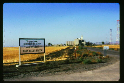 |
1944-1963 Operated by NBC 1963-1979 Operated by US Government USIA, ICA 1979-1983 Mothballed with caretaker crew 1983-1988 Operated by US Government USIA 1988 Decommissioned. Transmitter complement DX-1 RCA/Federal 200 KW DX-2 , DX-3 RCA/Federal 50 KW DX4 , DX-5 General Electric 100 KW DX-6, DX-7, DX-8 Collins 250 KW DX-9, DX-10 Continental 20 KW |
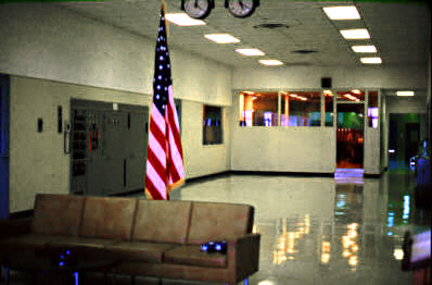
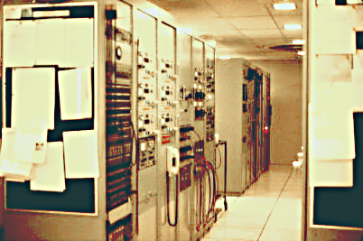
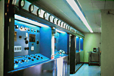
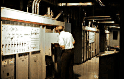
| North concourse. View from front door toward the control room. |
 |
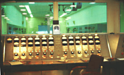 |
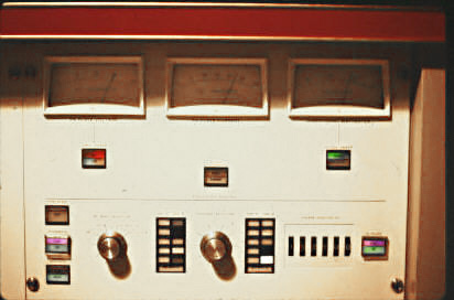
Master control console One vertical column for each transmitter White light - transmitter is on the air Top Meter - off air monitor from modulation monitor Bottom Meter - audio into transmitter 3 rows of switches, select various audio sources 4th row of switches, applies audio source to the transmitter Daven attenuator for control of audio level Next two rows of switches, remote control of transmitter. DX-4, DX-5, DX-6, DX-7 and DX-10 USB on air at time of photo. |
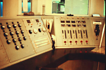
| Located to left of console. Audio Cartridge announcement selection, Monitor speaker selection, and station alarm panel white phone is intercom to various locations Antenna selection panel . Similar panels located to right side of master control console. Antenna selection panel, Monitor speaker selection and Two way radio remote control . |
 |
 |
Frequency control Epsco synthesizers. Other miscellaneous racks containing Collins 51J3 receiver, HP frequency counter Antenna interlock control Incoming program lines and amplifiers |
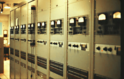
| Control room racks, One rack for each transmitter Gates Modulation monitor, UREI audio limiter, Kahn Symetrapeak . |
 |
 |
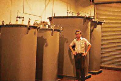
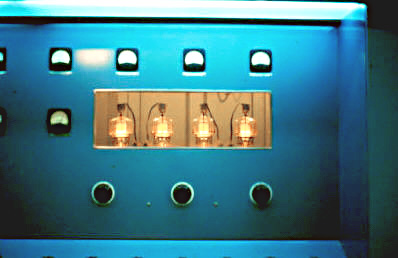
DX-1 200 KW RCA/Federal transmitter 200 KW RF final amplifier 50 KW RF driver. |
 |
Push pull / Parallel Modulator tubes. Three tubes on each side. |
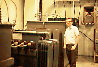
| Inside the High Voltage vault DX-1. Power supply transformers 2400 Volt primary feeders |
 |
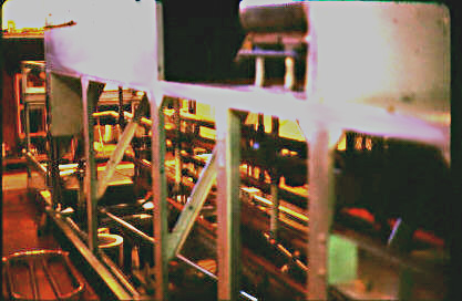
DX-1 High voltage vault Power supply filter chokes |
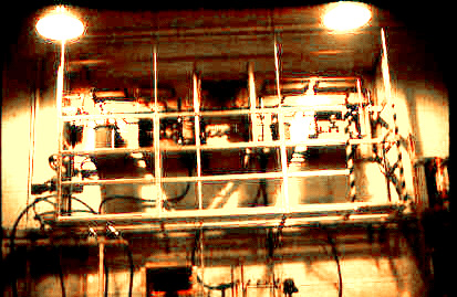
| DX-1 final PA tank. Grid tuning on top, Plate tuning below, Link coupled output to balanced 300 ohm open wire transmission lines |
 |
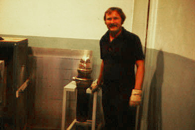 |
DX-1 Final RF amplifier Two Federal F-134 tubes Each tube weighs 80 lbs. Filament 25 Volts 650 Amps Water cooled, 40 gallons per minute required. 39" tall, anode 6" diameter |
| DX-2 and DX-3 RCA/Federal 50 KW transmitters with a common modulator. |
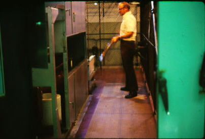 |
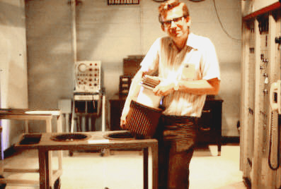
DX-1 Changing to a lower frequency 6 MHz coil being added to driver stage |
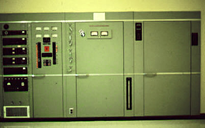
| DX-5 General Electric 100 KW G-100-A transmitter. Low level RF stages nearest, RF Power Amplifier. Access doorway, Modulator, Low level audio Power supply components DX-4 is identical and located in the East concourse. RF amplifier uses a pair of 5681 tubes driven by an 813. |
 |
 |
DX-5 304TH cathode follower audio drivers |
| DX-5 High Voltage transformers and chokes. 2400 Volt primary feeders |
 |
 |
DX-10 Continental 617-A Independent sideband transmitter DX-9 is identical, both transmitters removed and sent to VOA Greenville, NC. Final RF Amplifier tube - one 4CX35000 |
| DX-6, 7 and 8 Collins 821A-1 250 KW transmitters. |
 |
 |
Collins High Voltage vault Modulation transformer Power supply choke, Power supply transformer Oil cooled diodes 4160 Volt primary feeders |
| Collins HV vault. Crowbar catwalk, DX-6, 7, 8 crowbars featured unique triggered carbon ball gaps which reacted more rapidly to discharge the 15 kV power supply than would the more familiar electro-mechanical systems commonly in use. The higher speed was important in preventing damage to the transmitter's PA/modulator tubes and the numerous expensive water-cooled vacuum capacitors in the plate circuit, pi-line and balun |
 |
 |
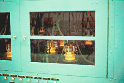
Collins 250 KW 4CV100,000 RF amplifier tubes (two in parallel) Modulator tubes (two in push pull) Vapor cooled tubes |
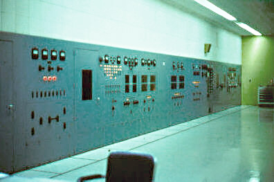
| Remote Collins console. Located in control room 15 KV 23 Amps 250 KW |
 |
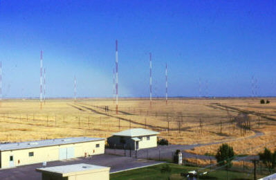 |
Rhombic antenna towers There are ten rhombic antennas, The rhombics were oriented toward Northern Asia Several were reversible in direction The reverse direction was used for Spanish Language Radio Marti programming to Cuba and for Spanish language programming to Central America in the 1980's |
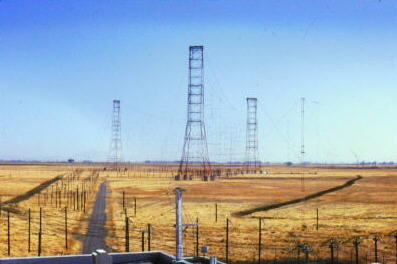
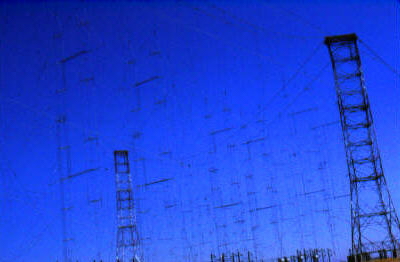
| Curtain antennas End towers 325 feet tall Center tower 305 feet tall 700 feet between towers |
 |
 |
Curtain antenna elements The Northern group of antennas were beamed toward Northern Asia The Southern group favored Oceania and the VOA relay station in the Philippines. The Rhombic antennas were oriented on similar azimuths |
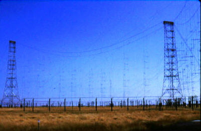
| Curtain antenna elements. Four antennas strung between each pair of towers |
 |
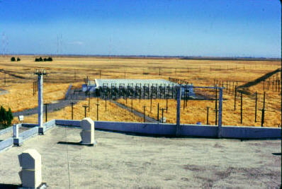 |
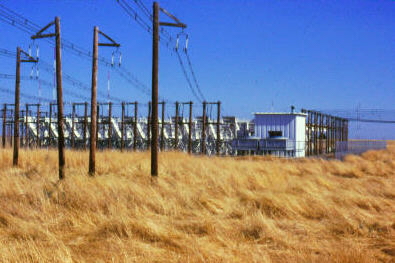
Antenna switchbay matrix Pneumatic RF switch capable of Switching any antenna to any transmitter |
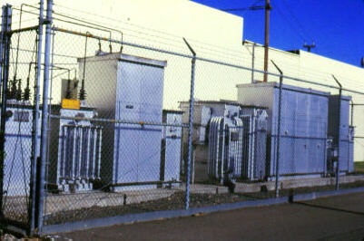
| RF switchbay. White building houses 250 KW dummy load. Nearest poles carry transmitter transmission lines into the switchbay, antenna transmission lines out either side |
 |
|
 |