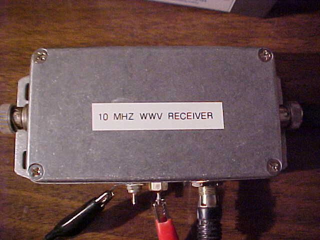
The receiver provides an accurate source of 10 MHz from WWV.
This is my version of the receiver.
| Home |
10 MHz WWV TRF receiver - W4CWG design
|
The W4CWG design for a 10 MHz TRF WWV receiver was discovered on line. The receiver provides an accurate source of 10 MHz from WWV. This is my version of the receiver. |
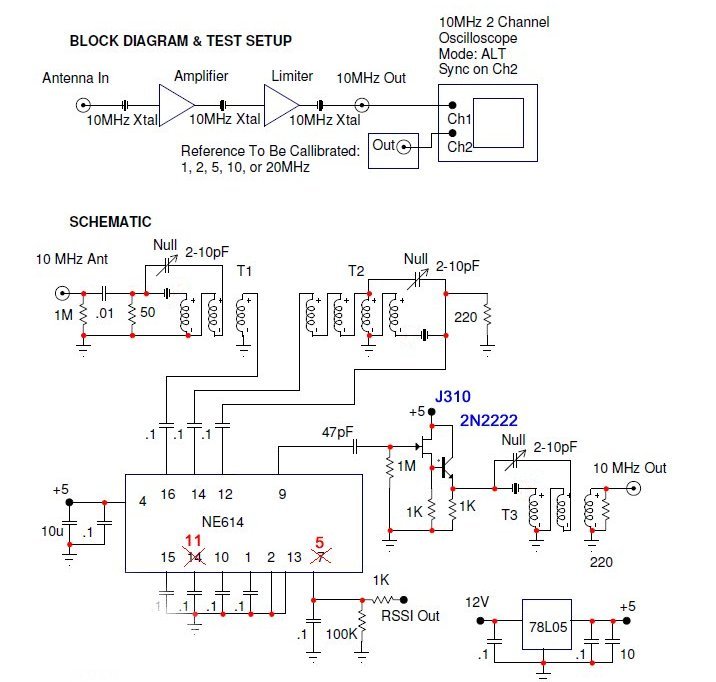
Schematic from W4CWG documentation. |
 |
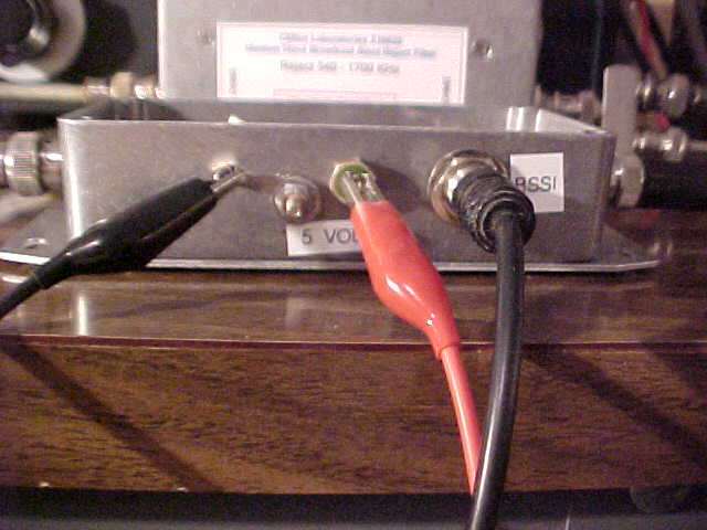 |
Side view RSSI, volts and ground. |
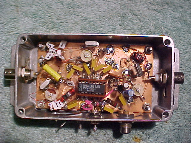
| The innards. Built using the Manhattan style of construction. |
 |
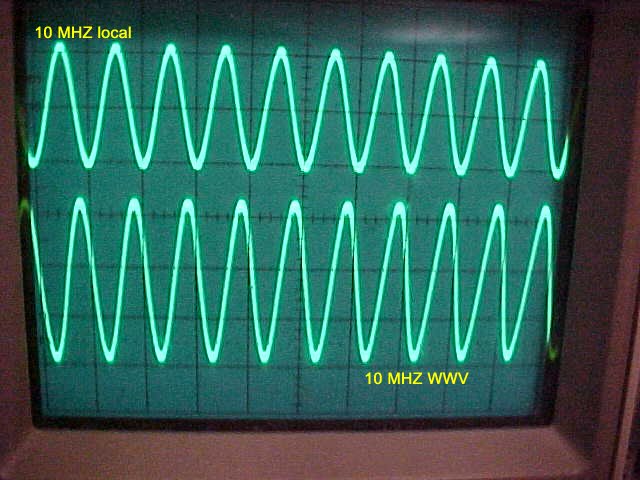 |
Scope view of the signals. I have been able to check the calibration of my HP3325A function generator to within a few tens of millihertz using the receiver. Great Box! Thank You W4CWG ! |
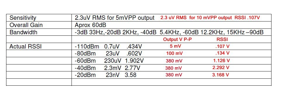
| Data from W4CWG documentation. Black numbers are W4CWG data, Red numbers are my data under similar input conditions. I also added the p-p voltage out of the receiver. |
 |